This guide assumes that you have successfully flashed a controller. Follow either the Windows or the Linux guide.
At the end of this tutorial you will have registered a controller (an ESP32), set up a peripheral (an LED) and turned it on.
Requirements #
In order to complete this tutorial you will need the following. The hardware is readily available on Amazon (list) and other online retailers.
- 1x ESP32
- 1x MicroUSB cable (prefer shorter cables)
- 1x Computer (Windows or Linux)
- 1x Breadboard
- 1x LED
- (Optional) 220 ohm Resistor
- (Optional) Jumper cable
Guide #
Connecting the Hardware #
First of all, connect the hardware as shown in the diagram below. This connects the LED with a pin of the ESP32 that can set its voltage to high (3.3V) and the other side to a ground pin. In our tutorial we will be using pin 32 as the output pin. Take care of the LED’s polarity. The flat side and the shorter leg show the negative side. This should be connected to the ESP32’s ground (GND) pin. To check if your setup works, temporarily connect the plus side (rounded edge and longer leg) to the 3,3V pin of your ESP32, if your variant has it.

Create an Inamata Account #
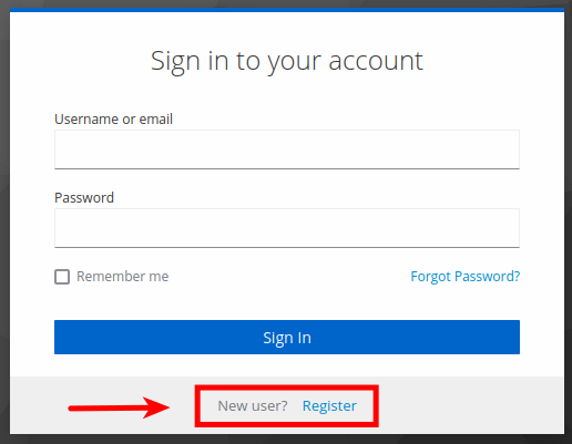
If you have not signed up already, create an Inamata account by going to the registration page. Enter your details, confirm your email address (check your junk folder) and you’re good to go. Otherwise, you can always register by pressing the Register link at the bottom of the sign in page.
Register a Controller (ESP32) #
If you have already registered a controller (Windows / Linux), skip to the next step (Add a Data Point Type). Otherwise, log into the app and then click Add Controller to open the add controller overlay. Follow the instructions to flash the controller with the Flasher app. This is separately described for Windows and Linux users. The app, for Windows and Linux, will flash the current firmware and save an authentication token on the device to allow it to automatically and securely connect to the Inamata server. If you have not already, connect your ESP32 to your computer with a micro USB cable.

Add a Data Point Type #

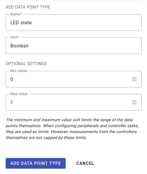
Press the blue add button at the top left the devices section and select data point type. Give it a name, such as LED state, and a unit, such as boolean or on/off. Optionally, set the minimum and maximum value to 0 and 1. This is a soft limit and will help you when controlling your peripherals. Click Add to save it.
You can view all data point types by going to the data points page in the devices section.

Add a Peripheral (Red LED) #
Go to the peripherals page via the sidebar and click add peripheral. In the first step, select the controller you want to add a peripheral to. This should have the same name you gave it in the Flasher app. Next, give it a name like Red LED. For peripheral type, select digital output as we’ll be setting one of the controller’s output pins to high to turn on the LED. Select a pin that can output a digital signal (ESP32 pin out reference). We recommend any between 16 and 33 but we will be using 32 in the following example. Press Add to add it to the controller.
The peripheral will show up in the peripheral table. Its state should change from Adding to Added once the command has been acknowledged by the controller.

Turn the LED On #
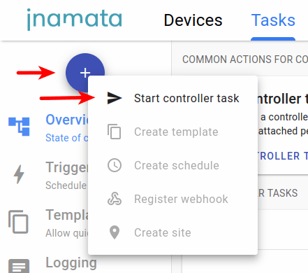
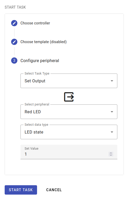
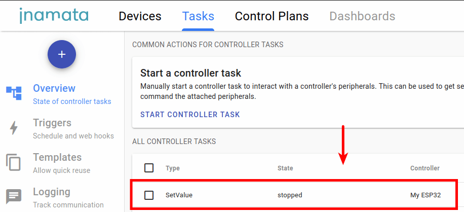
Go to the tasks section and press the blue add button to start a controller task. In the overlay, select the controller that you registered earlier and then skip the template selection. For the task type select Set Output. This will allow us to change the state of the peripheral. Select the peripheral you added earlier as well as the data type. Finally set the value to 1 and press start.
The task should appear in the controller task table. Its state should go from starting to stopped and in the mean time your LED should turn on.
Next Steps #
You have successfully turned on the LED. For your next step, why don’t you check out the Creating your first control plan guide where you can automate tasks and program the controllers visually.


