At the end of this tutorial you will have used graphical programming to created a control plan that commands your ESP32 to turn its LED on and then off after 3 seconds. The code runs on the server allowing you to combine multiple ESP32’s together. This tutorial continues where Turning on Your First LED leaves off.
Requirements #
A controller set up with an LED as a digital output. This is the result of the Turning on Your First LED tutorial.
Guide #
Creating a Control Plan #
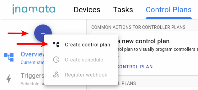
Open and log into the web app and go to the Control Plans section. Create a new control plan via the blue FAB (Floating Action Button) menu or with the common actions recommendation. Press edit to enter edit mode and drop in 5 nodes. These can be drag and dropped from the node palette on the left side once in edit mode.
- 1x Start node
- 2x Run controller task node (renamed to Turn on LED and Turn off LED)
- 1x Wait node
- 1x End node
Connect the nodes as shown in the diagram below.

Configure Run Controller Task Nodes #
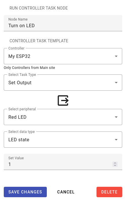
Once you have added and connected the nodes, double click the first run controller task node (Turn on LED). This will open its configuration panel. Here its name can be update to be more descriptive, such as Turn on LED and Turn off LED in the diagram above. Select the controller you registered in the previous tutorial. Next set the task type to Set Output followed by selecting Red LED and LED state for the peripheral and data point type respectively. For the first run controller task node set the Set Value to 1 and to 0 for the second one.
Configure Wait Node #
For the wait node, change the wait time in field to 5 and keep the time unit as seconds. Save the changes.

Test the Control Plan #
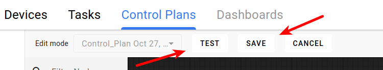
In the control bar press Save to save your changes. Next press Test to execute the control plan.
As in the image below, the nodes should change colors to indicate which node is currently being executed.

The control plan is being executed on the server. This means that you could close your browser and it would continue to run. To view running control plans, use monitor page to check their current state.
Congratulations #
You have successfully created a control plan and commanded a connected LED to turn on for a few seconds. Using this graphical programming approach will allow you to easily create complex scenarios while also being able to debug the control plan when it doesn’t do exactly what you intended.


