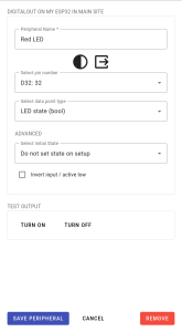
Digital outputs are the simplest peripherals used to command other devices. On ESP32 devices they can output a high signal of 3.3V which usually corresponds to the on state as well as the opposite low signal of 0V which is usually interpreted as off. This peripheral can be connect with transistors, MOSFETs, relays and other electrical devices that perform an action depending on an input voltage. The 3.3V signal can be shifted to a 5V, 12V or higher voltage with the help of a level shifter if the electrical device to be commanded operates at a higher voltage.
Status: Full support
Configuration of Digital Outputs #
The main aspects to be configured in digital outputs are the pin to be used and the data point type. Most pins on an ESP32 can be used as output pins. Exceptions to this are the highest pins, 34 to 39, as well as pins below 16 which can be used but may output signals on boot. For more details see the ESP32 pin out reference. The data point type helps set up set value controller tasks which gives them context for the connected device such as the unit it expects.
By default, a data point is saved each time the value is set. These data points can then be used in dashboards to show the state changes of the connected devices. This behavior can be disabled in set value controller tasks.
In the advanced section, the initial state of the digital output can be set to high or low. By default the output is not set. In addition, the digital output can also be configured as active low. This means that if it receives a 1, the output is set to 0V. Conversely, setting a value of 0 will set the output to 3.3V. This simplifies the logic in the rest of the system that expects a device to be turned on when sending a 1 even though the device expects the opposite.
Testing Digital Outputs #
It is possible to test the digital output peripherals directly from the configuration page without having to manually start a controller task. The turn on and turn off buttons will command the peripheral to turn on and off. Ensure that the settings have been saved as otherwise the old configuration will be used.
Related Documents #
To learn how to add a peripheral, follow the Turning on Your First LED with an ESP32 guide. This expects that you have already added a controller (Windows / Linux) as seen in our YouTube guide.


