Analog inputs are powerful yet simple peripherals to sense the state of other devices. On ESP32 controllers they read a voltage range from 0V to 3.3V using the internal ADCs (Analog-Digital Converters). This peripheral can be connected to light, temperature or pressure sensors that output a voltage corresponding to an environmental state. This voltage can then be linearly mapped to the unit the sensor is measuring in. Alternatively, directly return the measured voltage.
Use the read value and poll input controller tasks to read the peripherals value once or periodically. These tasks are also used in control plans and can be combined with if nodes to take an action depending on the measured value.
Status: Full support
Configuration of Analog Inputs #
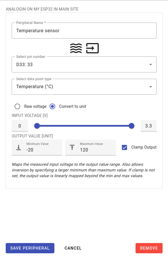
Besides the peripheral’s name, the main aspects to be configured in analog inputs are the pin and data point type to be used as well as the mapping of the read value. Give the peripheral a name of the device it is connected to such as temperature sensor or light probe.
The pins that can be used on an ESP32 are limited to 32 to 39 even though the ESP32 has a second ADC connected to pins 0 to 27. The reason the lower pins cannot be used is that ADC2 is disabled when Wi-Fi is enabled. The upper pins are connected to ADC1 which is unaffected by Wi-Fi being enabled. Internally the pins are multiplexed to their respective ADC but this does not significantly affect multiple analog input peripherals being active at the same time. See the ESP32 pin out reference for further details.
The data point type is needed to give the measured values context. The data point type’s name and unit are associated data point and are useful when creating dashboards. The limits of the data point type are not used in this context.
The read value can either be returned as a voltage or mapped to a unit measured by the sensor. Use the radio button to toggle between these behaviors. In the convert to unit mode, set the minimum and maximum voltage range. Then set the output values that these voltages correspond to. If clamp output is set, any voltage above or below the limits is mapped to the corresponding unit limit. It is also possible to invert the mapping, i.e., 0V equaling 120°C and 3,3V equaling -20°C. To do this, set the minimum unit value to the greater value and the maximum unit value to the lesser value.
Related Documents #
To learn how to add a peripheral, follow the Turning on Your First LED with an ESP32 guide. This expects that you have already added a controller (Windows / Linux) as seen in our YouTube guide.


