
This industrial WiFi controller, the Norvi Agent 1 – BT05 series, supports analog and digital inputs as well as commanding actuators via a relay. They can be bought directly from the manufacturer, Iconic Devices, and resellers sell similar variants. Learn to setup it up manually below.
Interfaces of the BT05 #
- 3 digital inputs
- 2 analog inputs (WIP)
- 1 relay output
- Button
- RGB LED
- Mini-USB
- 24V power input
Firmware for Norvi Agent 1 Devices #
The mainline ima_esp32 and ima_esp32_dbg firmware variants support this device. Use the Inamata Flasher app to flash the latest version (from 0.11.0) to connect it with the server. Currently only the relay output is fully supported. The remaining peripherals have backend support while the frontend support is still being worked on.
Manual Device Setup #
Relay Output #
Status: Full support
The relay allows larger loads to be turned on and off by the microcontroller. Use the two lower left ports on the Agent 1 labeled relay out. To use it add a digital output peripheral to the set up controller with the following configuration.
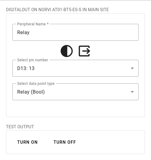
To setup the relay select pin 13 and a data point type that corresponds to the connected actuator.
Analog Inputs #
Status: Backend support, Frontend WIP
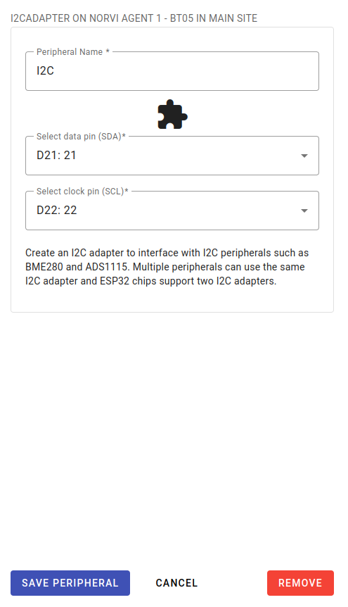
The analog inputs allow a voltages to be measured on 3 different channels. Internally the Texas Instruments ADS1115 sensor is used. Setting it up first requires creating an I2C adapter peripheral and an ADS1115 adapter peripheral. Then, one ADS1115 input peripheral has to be added for each channel. All ADS1115 input peripherals share the ADS1115 adapter peripheral.
Add an I2C adapter peripheral and select pin 21 for the data (SDA) port and pin 22 for the clock (SCL) port.
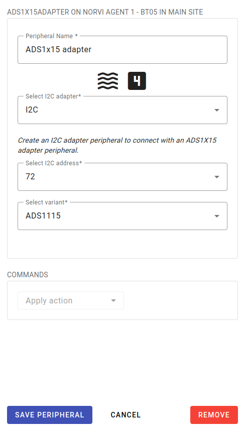
After confirming that the peripheral has been successfully added, add an ADS1x15 adapter peripheral. Select the I2C adapter that was added in the previous step and set the I2C address to 72 (0x48). As the variant select ADS1115.
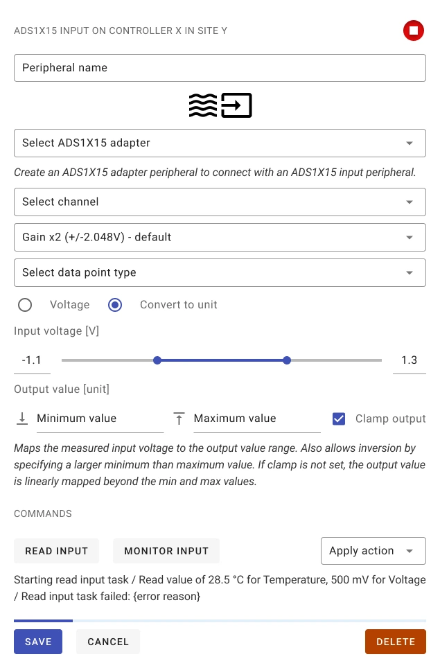
After confirming this peripheral was added successfully as well, add an ADS1x15 input peripheral. Select the added ADS1x15 adapter and then the appropriate channel. Channels 1 to 2 map to ports A0 to A2 on the bottom right of the controller. Set the gain to 1x for a range of 0 to 10 V. Then select the data point type that corresponds to the connected sensor. Finally select voltage or convert to unit and which mirror the analog input peripheral setup.
Button #
Status: Full support
The button located on the left face of the controller allows a user to send a signal. To use it add a digital input peripheral to the set up controller with the following configuration.
Select pin 35 as well as a data point type the corresponds to the button. Set the input type to floating and enable active low as 1 is returned when the voltage is high.
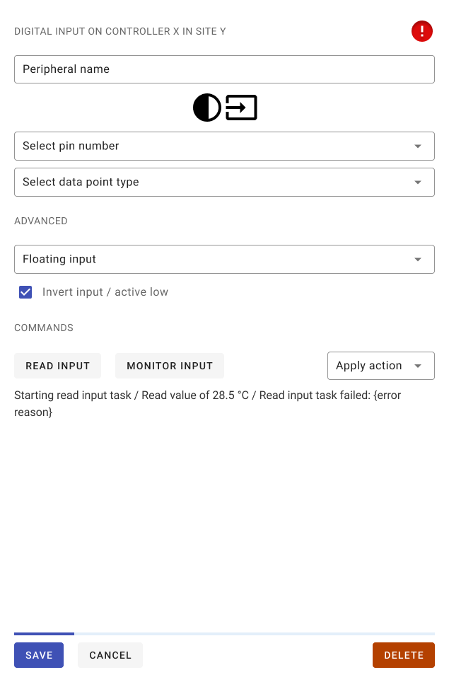
Digital Inputs #
Status: Full support
Select pin 18 for channel 1, pin 26 for channel 2 and pin 27 for channel 3. Select a data point type the corresponds to the connected sensor. Set the input type to floating and enable active low as 1 is returned when the voltage is high. The respective internal LED will turn on when the voltage goes high.
RGB NeoPixel LED #
Status: Full support, SetRGBLED Task (WIP)
The RGB LED allows a status with different colors to be displayed.
Select pin 25, an LED count of 1, the variant WS2812, and the color coding grb. The color or brightness of the LED can be set with an SetRGBLED task.
![]()
Further Support #
For further information on the Norvi Agent 1 – BT05 series see the official product page or the datasheet.


