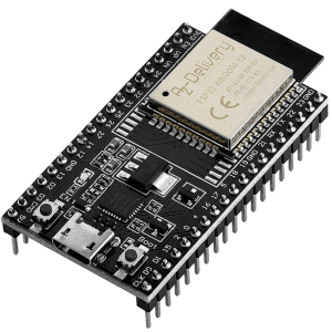
The ESP32 is a versatile and powerful microcontroller with WiFi and Bluetooth connectivity as well as a range of IO interfaces covering analog and digital inputs and outputs (ADC, PWM) and communication buses via I2C, SPI, UART, CAN and Ethernet. This is powered by a dual-core 240 MHz CPU and 520 KiB of RAM. On the DevKits, flash ranges from 4 to 16 MiB for the storage of the firmware and configuration data. The DevKits can be bought from a range of online retailers such as Amazon and eBay. For a deeper dive into the in- and output pins, refer to RandomNerdTutorial’s page. Learn to setup it up manually below.
Interfaces of the ESP32 DevKit-C #
- ~20 digital outputs
- ~24 digital inputs
- ~6 analog inputs
- ~16 PWM outputs (WIP)
- 2 UART interfaces (WIP)
- 2 I2C interfaces (WIP)
- Micro-USB
- 5V power input
Firmware for ESP32 Devices #
The mainline ima_esp32 and ima_esp32_dbg firmware variants support this device. Use the Inamata Flasher app to flash the latest version (from 0.11.0) to connect it with the server. Currently only the digital in- and outputs and analog inputs are fully supported. The remaining peripherals have backend support while the frontend support is still being worked on.
Manual Device Setup #
Digital Outputs #
Status: Full support
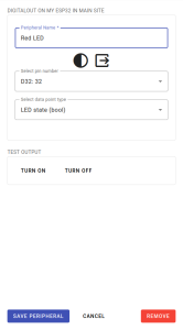
The digital outputs allows small electrical devices to be controlled and powered. LEDs can be turned on and off to indicate different states and transistors or relays can be commanded to turn larger loads such as motors and lamps on and off. Setting it up only requires creating a digital output peripheral.
Digital Inputs #
Status: Full support
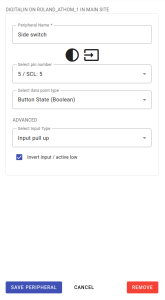
The digital input allows digital states to be measured. This is useful for HID elements such as buttons as well as simple sensors such as motion or light barrier sensors. Setting it up only requires creating a digital input peripheral. Here the pin as well as the data point type have to be selected. Setting the pull-up or down state as well as active low is optional.
Analog Inputs #
Status: Full support
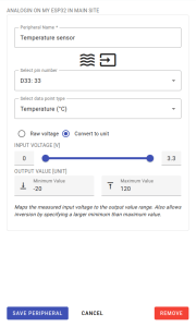
The analog inputs allow voltages to be measured on a multiplexed internal ADC. Setting it up only requires creating an analog input peripheral. After selecting a pin and an appropriate data point type, select whether the raw voltage should be measured or mapped to a unit. Mapping to a unit performs a linear conversion along a user-defined range.
PWM Outputs #
Status: Backend support, frontend WIP
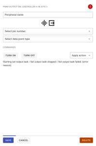
The PWM (Pulse Width Modulation) output allows analog output voltages to be approximated. The output pin is switched on and off at a high frequency with a configurable ratio to approximate a specific voltage when averaged out over time. This is commonly used to set the brightness level on LEDs as well as the power level of certain electrical motors. Setting it up requires creating a PWM output peripheral. Only the pin and data point type have to be set.
UART Interfaces #
Status: Backend support, frontend WIP
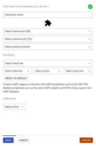
The UART interface allows sending and receiving messages to and from other UART devices. Setting it up requires creating a UART adapter peripheral. Additional devices can then be added on top of this interface, such as the CSE7766 power meter.
I2C Interfaces #
Status: Backend support, frontend WIP
The I2C interface allows sending and receiving messages to and from other I2C devices. Setting it up requires creating a I2C adapter peripheral. Additional devices can then be added on top of this interface, such as the ADS1115 analog inputs, Atlas Sensor pH, EC and turbidity meters or the BME280 or BH1750 air sensors.
Further Support #
For further information on the ESP32 DevKit, see the RandomNerdTutorial’s introduction page or ask for help on our support forum.


